Are you trying to use an inductive sensor but you have an interfering conductor nearby? This problem can be resolved by inserting a sheet of ferrite material between the interfering metal and the sensor coil.
Inductive sensing technology measures proximity of conductive materials, such as nearby pieces of metal. Metal at a distance of up to approximately one sensor coil diameter influences the inductance reading of an inductance-to-digital converter (LDC), such as the LDC1000.
Similar to its use in electric transformers, ferrite material can be used in inductive sensing systems to concentrate and redirect magnetic flux. The high permeability and low conductivity of a ferrite increases the dynamic range of a sensor and therefore extends its usable range. The ferrite also helps shield the sensor from undesired metal in the proximity of the sensing coil. This interfering metal could be a large static piece of metal, such as a metal casing, or another moving part in the proximity of the sensor.
To evaluate the effects of a ferrite backing, I set up a system in which I measured the output of a 24-bit inductance-to-digital converter while changing the distance between an aluminum target and a coil. I then positioned an interfering metal and/or a sheet of ferrite material on the other side of the coil.
I used the following components (in order of assembly):
- Target: (55mm x 80mm aluminum, 1.3-mm thickness)
- Sensor PCB coil: (50mm diameter, 120 turns/layer, 2 layers, 4 mil trace/space) with a 330pF sensor capacitor
- Ferrite sheet: Würth Elektronik Flexible Sintered Ferrite Sheet (part number 354 003), (55mm x 80mm)
- Interfering metal: (55mm x 80mm aluminum, 1.3 mm-thickness)
I measured the impact of the interfering metal and the effectiveness of shielding with a ferrite material.

Measurement 1: Impact of the interfering metal
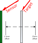
Any unwanted conductive material in the proximity of the sensor coil will affect the output of an LDC by reducing the dynamic range of the system. To illustrate this, I moved a target in front of the coil at a distance of 2.5mm (5% of coil diameter) to 25mm (50% of coil diameter) in 500μm steps, as shown below.
Next, I introduced an interfering conductor on the opposite side of the sensor and moved the target from 2.5mm to 25mm, as shown below.

The red line in the graph below shows the LDC output without the interferer, and the purple line shows the output when the interferer was present. Without the interferer, the LDC output code changed by 67,023 codes, as the target moved from the minimum distance (2.5mm) to the maximum distance (25mm). With the interferer, the total change in codes was reduced by 6,381 codes – a 10.2% reduction in dynamic range.
This decrease in useable dynamic range can be even worse if the interferer is a larger conductor or if it is closer to the sensing coil.

Measurement 2: Shielding the interfering metal with a ferrite
In the second experiment, I covered the back side of the sensor with a ferrite shield.

The purpose of the ferrite is to channel the magnetic field strength toward the target and to shield from the interfering metal. The green line below shows the effect of the ferrite. Under these test conditions, I measured a difference of 70,898 codes between the minimum and maximum target distances, an increase in dynamic range of 5.8%. This measurement shows that adding the ferrite not only canceled the effect of the interfering target, but even boosted my dynamic range compared to the first measurement without an interferer.

Ferrite benefits
Adding a ferrite backing can be an effective method to channel the magnetic field in order to boost the dynamic range of an inductive sensor and to shield it from interfering metal. The table below summarizes the findings and shows that a ferrite backing can be used to eliminate the interference from a conductor. In fact, the ferrite even improves the dynamic range versus the case with no ferrite and no interferer.
| interfering metal = no, ferrite = no | interfering metal = yes, ferrite = no | interfering metal = yes, ferrite = yes |
output code | 109,427 | 141,438 | 86,597 |
output code | 176,450 | 201,630 | 157,495 |
output code change | 67,023 | 60,192 | 70,898 |
Percent change in dynamic range | 0 | -10.2% | 5.8% |
Additional resources:
- Learn more about inductive sensing.
- Read more inductive sensing blogs, including how to design a PCB coil for inductive sensing in five minutes.
- Check out all the inductive sensing design tools.
- Search for answers and get help with your inductance-to-digital converter design in our Inductive Sensing forum.