In my last DAC Essentials post, I discussed the source of output glitching in precision digital-to-analog converters (DACs). These output pulses can disrupt system behavior when you’re expecting a linear transition as you step up codes. Let’s take a quick look at a glitch pulse from my previous post as a refresher:
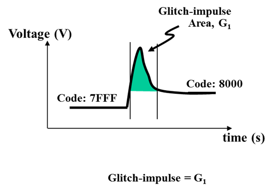
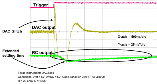
DAC output glitch is an "energy" defined by the width and height of the pulse (shown in green). Manipulating the shape of this glitch may be good enough – depending on the system requirements. Adding a simple RC filter after the DAC output attenuates the amplitude of the glitch but increases settling time. However, the glitch "energy" (area under the curve) remains the same. Below is an example of a DAC crossing a major carry transition showing the output before and after an RC filter.
You should choose the appropriate resistor and capacitor ratio for the RC filter by looking at the glitch period and selecting a cutoff point a decade or so prior. When it comes to picking the component values, you’ll want to keep the resistor value small to avoid a large voltage drop with a resistive load. From the resistor selection, the capacitor value can then be chosen from the desired RC ratio.
Another approach to reduce glitch is using a track and hold amplifier technique. This method is a bit more tedious, as it requires strict switch timing, along with external components leading to higher cost and more board space.
Using an external switch, a few passive components, and amplifier, you can remove the DAC output glitch completely and replace it with a small transient from the new S/H switch. This new short transient can then be attenuated with a first order low pass filter stage. A basic diagram is shown below.
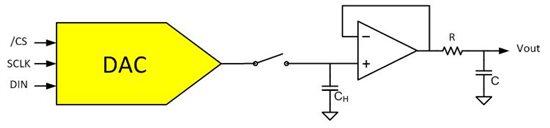
The system design structure is fairly straightforward. The switch is open as the DAC crosses over a major carry transition. This is where the glitch will take place. Once the voltage transition completes, the switch is closed, charging the CH sampling capacitor to the desired value. The capacitor continues to hold the new voltage as the external switch opens while the DAC updates its output again. This allows you to remove the glitch (in theory) without increasing the settling time.
Here are the pros and cons of the two solutions I've discussed:
- If the system can live with increased settling time and needs attenuation on the glitch impulse amplitude, a simple RC filter may do the trick.
- If the system needs the glitch completely removed, a track & hold amplifier solution may work.
Of course, the other option is to steer clear of R-2R DACs and design with a string DAC solution to avoid large glitching altogether. Just know that doing so may force you to tradeoff other DAC specs.
If you’re new to the DAC Essentials series and found this post interesting, be sure to check out our previous posts:
- What’s with all this glitch-ing?
- The resistor ladder
- String theory
- Static specifications & linearity
- The pursuit of perfection