Looking for more information about digital isolators? We’re here to help. Based on TI E2E™ Community feedback, we compiled a list of the most frequently asked questions about digital isolator design challenges. We hope this list will provide useful insights when isolating signals and power.
1. What is the difference between basic and reinforced digital isolators?
Basic digital isolators have to pass a suite of tests according to component-level standards such as Deutsches Institut für Normung (DIN) V Verband der Elektrotechnik, Elektronik und Informationstechnik (VDE) V 0884-11. DIN V VDE V 0884-11 defines the voltage levels that the isolator can withstand, such as the maximum surge isolation voltage, VIOSM; the maximum transient isolation voltage, VOITM; and maximum repetitive peak isolation voltage, VIORM (as explained in the white paper, “High-voltage reinforced isolation: Definitions and test methodologies”). Reinforced digital isolators, in addition to passing these tests, have to pass a minimum surge voltage test level of 10,000 VPK.
2. Can you power the two sides of a digital isolator with different voltages?
Yes. Digital isolators can be supplied voltages within the recommended operating conditions on both sides of the device. Since an isolation barrier separates the two sides, each side can be sourced independently with any voltage within recommended operating conditions. For example, it’s possible to supply ISO7721 VCC1 with 3.3 V (which is within 2.25 V to 5.5 V) and VCC2 with 5 V (which is also within 2.25 V to 5.5 V). This way, you can use the digital isolator as a logic-level translator in addition to providing isolation. The two sides of the isolator are independent.
3. Can a digital isolator signal voltage be different from its power-supply voltage?
No. The input/output signal voltages of digital isolators depend on its applied power-supply voltage. Hence, for the digital isolator to be compatible with the devices it interfaces to, it’s best to keep signal voltages similar to the isolator power-supply voltage. For example, when the ISO7721 is powered with 5 V and interfaces to a microcontroller (MCU), it is important that the MCU signals are also operating at 5-V logic levels.
4. What is the logic state of a digital isolator with no input signal?
When the input channel of a digital isolator is unpowered or the pins left floating, its respective output pin takes a predefined state (called the default state or fail-safe state), which can be either low or high depending on the device chosen. The suffix “F” in a device part number indicates the default state of output channels of the isolator. For example, no F in the ISO7721DWR indicates that the default state for this device is high. Similarly, the F in the ISO7721FDWR indicates that the default state for this device is low.
5. Can you leave unused channel pins on a digital isolator floating?
No. Input pins of unused channels of a digital isolator can be left floating for testing purposes, but in applications, leaving the unused pins floating could make the product less immune to noise.
The floating pins are especially prone to noise pickup when the system is subjected to electromagnetic compatibility (EMC)/immunity tests. To make the system immune to such noise, it is best to tie the channel inputs to their respective default logic states.
For example, for the ISO7721DWR, it is best to connect the unused signal input pin to its VCC through a pull-up resistor (preferably with a 4.7-kΩ resistance). For the TI ISO7721FDWR, it’s best to connect the unused signal input pin to its GND pin and leave. For both devices, the output pins of all unused channels are best left unconnected.
6. How can you determine the power consumption of a digital isolator?
You can calculate the power consumption of a digital isolator from specifications listed in their data sheet. Locate the Supply Current Characteristics table for your corresponding supply voltage (2.5 V, 3.3 V, 5 V). Within this table, find the data rate closest to the speed of your application signals. The data sheet will list the current consumption for that particular data rate, as a separate total for each side of the isolation barrier (ICC1 and ICC2). Adding these two currents together gives you the total current consumption of the device under that operating condition. Dividing it by the channel count of the digital isolator gives you the per-channel current consumption. Some data sheets also provide this total supply current per channel separately. For example, the ISO7041 data sheet shows a typical current consumption of 4.2 µA under the Total Supply Current Per Channel parameter, which is the ICC1(ch) plus ICC2(ch) currents.
7. How do you generate isolated power for a digital isolator?
There are several options to generate isolated power for a digital isolator; the best solution depends on the specific application needs.
One option is to use a transformer driver like TI’s SN6501, which operates in a push-pull configuration with a transformer and optional rectifying low-dropout regulator on the secondary side (Figure 1). The SN6501 is capable of delivering as much as 1.5 W to provide isolated power. This device has the flexibility for use in almost all applications because the transformer and turns ratio can provide the necessary isolation rating and output voltage for the power supply. You can use the SN6505x instead of the SN6501 for as much as 5 W of output power if you need isolated power for additional devices. The SN6505 has extra protection features such as overload and short circuit, thermal shutdown, soft start, and slew-rate control, enabling a robust solution.
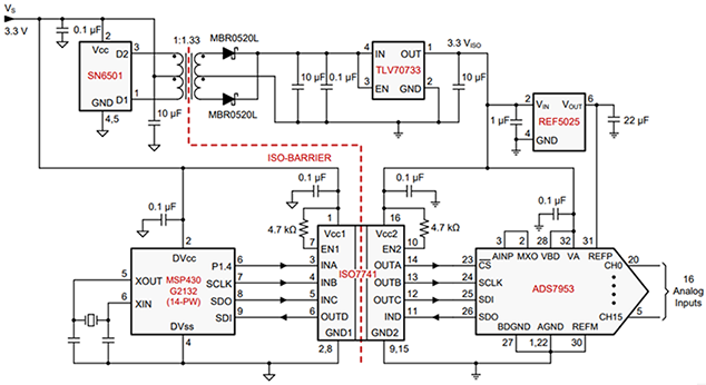
Figure 1: Isolated power for the ISO7741 using the SN6501
Another option for space-constrained applications is the ISOW78xx family of devices, including the ISOW7841, which provides signal and power isolation in a 16-pin small-outline integrated circuit package. This combination, as featured in Figure 2, is compact, doesn’t require a transformer and makes certifications easy.
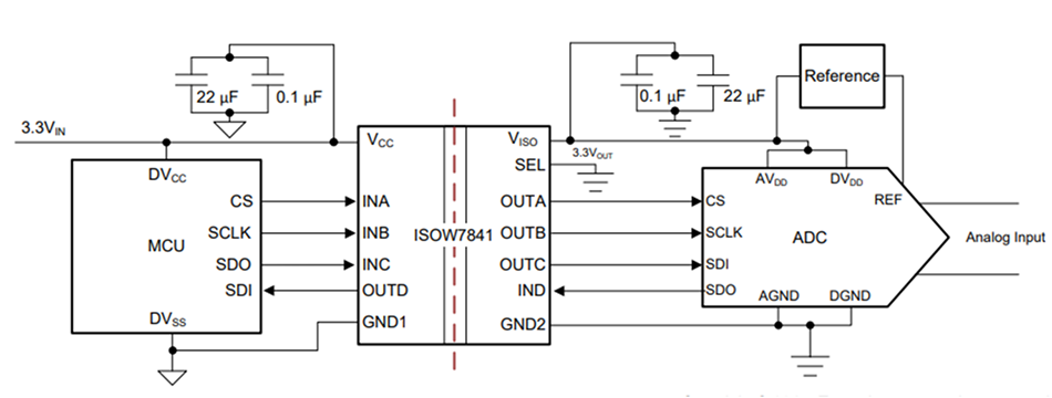
Figure 2: Digital isolator with integrated signal and power using the ISOW7841
What questions did we miss?
If you’re looking for more information about digital isolators or have a question you would like to see added to this list, leave a comment below and help us keep the conversation going.
Additional resources
- Learn more about TI’s isolation solutions and its digital isolators portfolio.
- Read “Considerations for Selecting Digital Isolators.”
- Our isolators are certified. Are yours?
- Check out the forum post, “How do I read TI’s digital isolator part numbers?”