Motor control is an essential part of electric vehicles, which generally use permanent magnet AC motor (PMAC) or induction motors. There are advantages to both types, as well as trade-offs.
PMAC motors can use resolvers or encoders. A resolver converts mechanical motion into electrical information pertaining to the absolute rotary position. It consists of a primary winding and two secondary windings. The secondary windings are on a stator at a 90-degree angle relative to each other, whereas the primary winding is on the rotor. Other types, such as variable reluctance, have all three windings on the stator.
When an excitation current is applied at the primary winding, the sine/cosine secondary windings will output the same frequency signal while being 90 degrees out of phase. You can use the magnitudes of the two secondary windings to calculate the exact position of the shaft relative to the stator.
Figure 1 shows an example of a resolver-based circuit with the ALM2402F-Q1.
| Parameters | Description | Typical range |
| Input voltage | Input voltage to the resolver primary coil R1/R2 | 3 VRMS-7 VRMS |
| Input frequency | Excitation signal frequency applied to the resolver primary coil R1/R2 | 1 kHz-20 kHz |
| Transformation ratio | Ratio between the resolver’s primary and secondary coils | 0.2 V/V-1.0 V/V |
| Input impedance | Input impedance of the resolver (resistance-inductance) | 30 Ω, 80 mH |
| Phase shift | Phase shift between the resolver excitation signals and sine/cosine signals from the secondary coil | ±25 degrees |
| Pole pairs | Number of sine/cosine output cycles per mechanical rotation | 1-3 |
| Supply voltage | Supply voltage provided to the analog front end | 12 V-26 V |
| Accuracy | Output angle readout accuracy | ≤0.1-degree error |
| Resolution | 16 bits | |
| Temperature | System temperature | -40°C to 125°C |
| Amplitude | Desirable sine/cosine amplitude | 3.3 Vp-p |
| Frequency | ||
| Attenuation | Resolver voltage attenuation 0.4 Vp-p | 0.4Vp-p |
Table 1: Typical parameters for resolver-based measurements
One of the critical tasks in choosing the right device to drive the primary coil is to assure the minimum slew rate for the excitation amplifiers so that you can avoid slew-induced distortion. Equation 1 calculates the excitation voltage as the ratio of the sine/cosine amplitude over the attenuation:
(3.3/0.4) = 8.25 Vp-p (1)
Equation 2 expresses the minimum slew rate to avoid distortion:
SR = 2*π*Vp*f = [(2*6.28*(8.25/2)*20000)]/1E6 (2)
Equation 2 yields 0.52 V/μs.
Figure 2 shows the minimum slew rate required for the excitation amplifier.
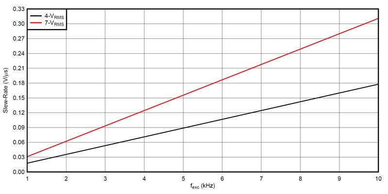
Figure 2: Minimum slew rate needed for an excitation amplifier vs. frequency
Resolver-based measurement methods
There are two common methods for resolvers: a software-based resolver-to-digital converter (RDC) with a microcontroller (MCU) and an integrated circuit RDC. The MCU generates a pulse-width modulation (PWM) signal that is modulated into a sine wave. Active low-pass filters then filter out the PWM carrier frequency and rid the system of undesirable harmonics, leaving only the excitation frequency component for the primary circuit. Active high-pass filters remove DC offsets.
Once the signal is filtered out, it needs conditioning using high-output current amplifiers, which is again achievable with a discrete solution using low-noise op amps such as the OPA2197, along with BJT transistors or integrated dual power amplifiers like the ALM2402F dual op amp. The ALM2402F offers not only a high output current (400 mA) but also thermal shutdown and a current limit, along with an integrated overtemperature fault flag.
The other area of interest is the aforementioned analog front-end portion of the circuit, which comprises three difference amplifiers. The first amplifier monitors the output of the excitation amplifier to detect phase lags caused by low-pass filters (through the MCU), or faulty conditions, which may have been caused by the excitation amplifier. The other two amplifiers are used to buffer the sine and cosine signals coming from the secondary windings of the resolver. An example of this is shown in Figure 3, which represents a typical analog front end for a resolver-based application.
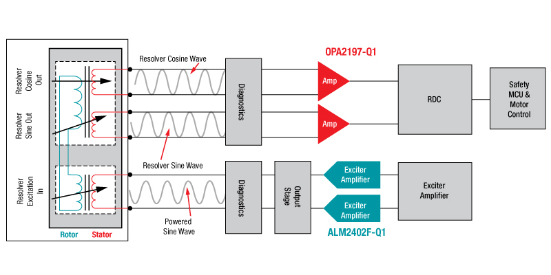
Figure 3: Typical resolver front end
The key to designing a good difference amplifier is the matching of the external resistors used for gain control. While discrete op amps such as the OPA2197-Q1 provide very good DC performance (low input offset voltage and drift), common-mode rejection will depend on resistor matching. A pair of 0.005% matched resistors achieves 86 dB.
Safety (ASIL) requirements
Another important aspect to designing a resolver circuit is the need to abide by functional safety standards. Although there are several standards across many sectors, automotive hardware engineers must adhere to International Organization for Standardization 26262 safety requirements to support Automotive Safety Integrity Level (ASIL) A to ASIL D. ASIL is a critical part of the design in applications like electric power steering, transmission gear boxes, braking systems and advanced driver assistance systems. The point of complying with functional safety standards is to mitigate risk in case of a malfunction. If failure occurs in a motor-control system, the functional safety part of the circuit can detect a faulty condition and respond accordingly to remedy the problem. One way to implement a safety circuit is to use two components for redundancy in the excitation part of the circuit within the resolver. One integrated such as the ALM2402F-Q1, the other in a discrete fashion like the OPA2197-Q1.
Resolvers have become more popular in recent years because they can operate in harsh environments, withstand high temperatures and provide accurate measurements. Selecting electronic components requires extra care, however, since they are usually located a distance away from the resolver itself, which makes noise immunity and common-mode rejection ratio paramount to achieve the desirable performance.
Texas Instruments precision amplifiers (including the ALM2402F-Q1 and OPA2197-Q1) have integrated electromagnetic interference (EMI) filters within the input stage to minimize the effects of undesirable radio-frequency injection. To learn more, visit the resources below.
Additional resources:
- Read the application brief, EMI-Hardened Operational Amplifiers Reduce Inaccuracies.
- Explore the discrete resolver front-end reference design with C2000™ microcontroller and ±0.1° accuracy.
- Learn more about TI solutions for servo drive position feedback.